Daylight Running Lights (DRL) Triumph Stag
April 2020
Having decided to fit Day light Running lights to my Stag I did not want to fit external LED’s as they look too white, modern and not really suitable for a 70’s classic.
I looked into the vehicles which have 21w DRL’s built into their side lamps VW, Ford, Peugeot & Fiat vans. They use bulbs similar to the brake/stop bulbs. I wondered if fitting these to the stag sidelight unit would be possible.
The first thing to do after disconnecting the battery was to remove the sidelight unit, this is done by removing the dip beam headlamp unit and the rear of the sidelights can then be accessed. The sidelights are secured by 3 x nuts. On removal and after studying the light unit I decided that I did not want to change the side light bulb holder, instead I would fit an additional BA9 holder for the side lamp bulb and use the original side lamp holder for the DRL. In the original set up the side light bulb lines up with the centre focusing strip on the lens, I wanted the new side lamp bulb holder to do the same and with the centre strip of the lens.
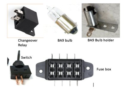
Here is the list of items I sourced for this project
1 X fuse holder 10A Fuse
2 X changeover relays
2 X 21w motor cycle BA9 21w bulbs (I may change these to LED’s)
2 X BA9 bulb holders
1 X Switch
Various lengths of wiring
Crimp connectors
Cable ties
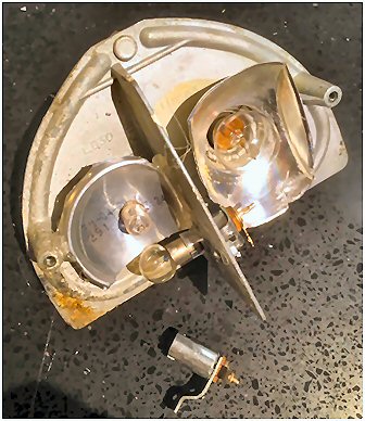
As can be seen from the photo below I have drilled a hole in the lamp unit dividing plate and fitted the new BA9 holder to allow its bulb to line up with the lens focusing strip. I fashioned a reflector for the DRL from the base of a drinks can, this was glued in place and wiring fed through the back plate.
For DRL’s to work properly they should not be on when the sidelights or the headlamps are in use. To facilitate this function, I have used two Changeover Relays.
Here follows a description of how a changeover relay works.
A Changeover relay has five terminals usually numbered 30, 85, 86, 87 & 87a. Terminals 87 & 87a have a common (30) with no power going through the relay terminals 87a and 30 are connected. When the relay is powered up by providing a feed to terminal 86 and an earth to terminal 85 terminal 87 connects with 30. I hope that explanation is not as “clear as mud”.
In my wiring diagram below it can be seen that I have used two changeover relays R1 & R2 and here is the basic explanation of of how I wired the system.
RELAY 1 (terminal numbers on drawing)
12v feed taken from the “fuel pump cut out switch” through a dashboard switch to terminal 86, this is an ignition powered live.
RELAY 2 (terminals are numbered as for Relay 1)
12v feed from side lamps to terminal 86.
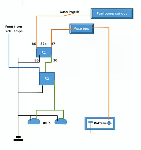
With no headlamps or side lamps on power to R1 will allow the DRL operate.
When the side lamps are switched on it will cause the R2 to operate thus switching off the DRL’s.
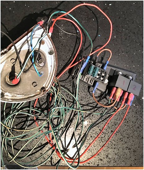
The photos below show my wiring (prior to wrapping), fuse box, relays & back of the side lamp assembly.
 |
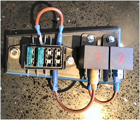 |
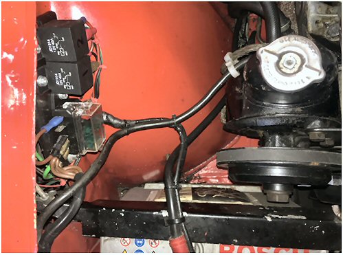
I fitted the fuse and relay board to the front of the offside inner wing as shown in the photo below.
The wiring has been wrapped in PVC where required
For information, the fuse box also feeds the headlamp relays – another project (2 x green fuses).
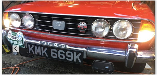
The following photo shows the DRL’s in operation.
This modification is totally reversible. If anyone needs any further information, please drop me an email.
Danny Stroud
dannystroud@sky.com
TSSC Area Organiser North East Scotland
SOC Deputy Co-ordinator AO Grampian
Grampian Stags
1972 Mk1 Stag
1967 Mk3 Spitfire
1953 Ford Anglia