UPGRADING THE Mk1 TRIUMPH STAG HEADLAMPS
by Danny Stroud
Initially I did not set out to upgrade my headlamps it came as a result of stripping down and rebuilding my steering column, there is another article on this.
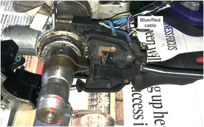
When I removed the headlamp dip switch I put the multi meter across all the terminals to see what each individual terminal/wire operated.
I noted that on the dip action a blue/red wire completed a circuit (blue/red wire is the Lucas denoted wire colour for dip beam). See Photo as fitted to steering column.
I was surprised to note that on Full Beam switch setting only the blue/white wire (colour for full beam) completed the circuit and the blue/red contact was not energised. This I found strange as on full beam setting the dipped lights are also on. Further investigation was needed.
Internet research has shown that the MK1 Stag has the same Dip/Full beam switch as the Triumph 2000 Mk2. The Stag Mk2 has its own switch which has no blue/red wire although the contact is present. There is a forum post on upgrading the switch by adding an additional wire to the MK2 switch.
The reason that the dip beam lights remain on when on full beam is because the main power feed (blue wire) from the light selector switch to the dip switch has a spliced take off directly to the dipped beam lights. The blue/red cable from the dip switch terminates at the connector plug/block under the dash board and above the steering column.
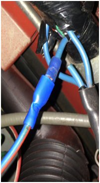
To get the dipped feed to go off when the full beam is selected this blue wire to the dipped lights needs to be cut and to power the dipped lights when the dip is selected a new wire needs to be connected from the blue wire to the blue red from the dip switch.
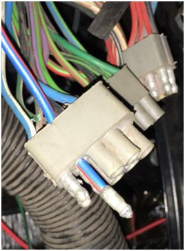
For this new wire I used a length of blue/red cable and joined them using spade connections. The other end had a spade connection which fitted in to the multi connector block/plug from the dip/full beam/indicator switch. This connector block/plug connects t the corresponding one on the main loom; this has to be drilled to accept the new blue red wire as shown in the photos.
 ..............
There are many ways described on various forums how to upgrade your head lights to four main beams, this what I decided to do.
My aim was to have four main beams and two dipped beams and to also reduce the load on the main light switch and the stalk dip/full beam switch. On the Mk1 Stag the fog lamp switch is part of the main lamp switch, when activated the main beam and dipped beam lamps are deactivated. Back in the day many cars were fitted with the Lucas Square 8 lamps had a matched set comprising of one fog lamp on the off side and one spot lamp on the near side, this is what I have fitted on my car.
To facilitate the upgrade, I ordered the following parts.
Below is a wiring diagram for my set up, I have the relays powering:
No1 relay, n/s dipped beam H4 headlamp
No2 relay, both inboard H1 full beam headlamps
No3 relay, both Lucas Sq8 lamps
No4 relay, both outboard H4 full beam headlamps
No5 relay, o/s dipped beam H4 headlamp

The different wiring colours on the drawing above are only to make it easier to follow individual cables. The actual colours used are described later.
The drawing (borrowed from elsewhere) below shows the relay setup.
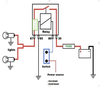
I feel that my set up gives a degree of failsafe if a relay or fuse fails, also having two feeds from the fuse box helps with redundancy.
When I fitted the lamps to the rims I found that the holes for the lamp lugs were not correctly located on the fixing rim as the new lamps are H4’s and the old lamps were H1’s, I had an original old Lucas lamp and bowl and the bowl needed slight modification to allow the lamp to seat correctly. I filed the slots for the lamp lugs on the rim a few mm anticlockwise from the original slots. This ensured that the horizontal line on the lamp lens was horizontal with the ground.
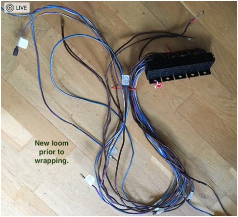
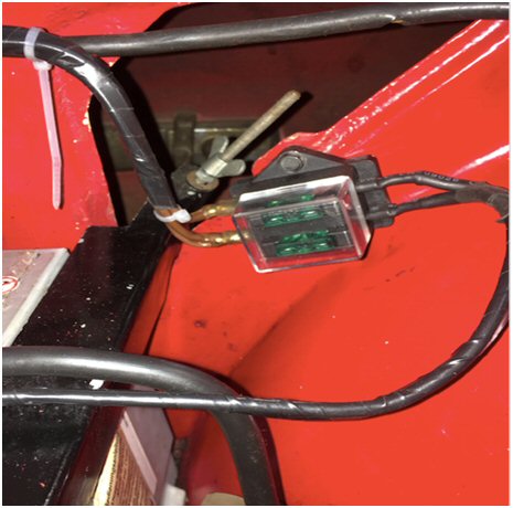
I fitted the the main feed fuse box on the offside inner wing next to the triangular access hole. The five relays were fitted to the nearside of the front panel and inside the engine compartment, the wiring feeds through the upper round lightning hole which was protected by a grommet. A new extra loom arrangement was made up and was covered with black tape to make it look more original.
The wiring colours I have used were;
Brown: Live feed from battery from new fuse box.
Blue/White: Full beam lamps switching and power.
Blue/Red: Dipped beam lamps switching and power.
Purple/Yellow: Fog lamps switching and power.
Black: Earth.
The headlamp fuses in the main fuse (OE) box have been replaced with 5A fuses. Each relay has been fitted with a 15A fuse. The main feed from the battery is protected by 30A fuses.
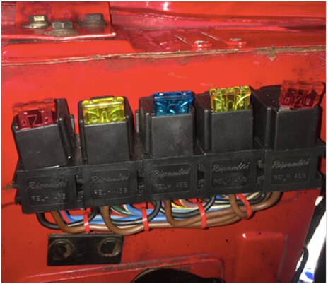
The next photos show the final positioning of the relays on the nearside of the front panel and the fuse box on the off side inner wing.
 .....
.....
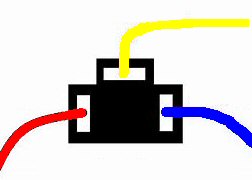
The new H4 bulb plugs came with blue, red & yellow wires
For the H4 bulb wiring
THE PINS (VIEWED FROM THE REAR)
Blue/ Red to Yellow, Black/earth to Red, Blue/White to Blue
I would like to thank all the enthusiasts, especially Staggering About, Jonno & Jakesmig, that have gone before me with their descriptions of specific setups which has helped me develop mine.
I hope you find this information useful a lot of it has also been documented by other enthusiasts. If you need to ask me anything please email me at dannystroud@sky.com . Also have a look t all the other technical information on the Grampian Stags Website http://www.grampianstags.net/ .
Thanks to Alan Sharpe SOC AO for the Grampian Area for hosting the website.
Danny Stroud
TSSC AO North East Scotland
SOC DAO Grampian
1972 Mk1 Stag
1967 Mk3 Spitfire
1953 Ford Anglia
Some links
https://www.youtube.com/watch?v=q7eEx5ci_ts
http://www.tscusa.org/tech/6_Lights_Illumination_MichaelLink_2017_Q1_Winter%20Issue%2094.pdf