
Water Pump Rebuild
Note one inlet manifold bolt already replaced with heli-coiled stud!
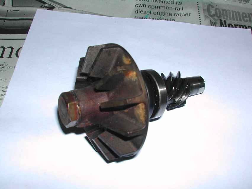
Disassembly revealed a 12-vane pump!
I had originally intended to install a new pump that I had acquired from a friend. However, further investigation led me to be suspicious of the quality of new pumps and so I ended up rebuilding my original.
It all started when I noticed that there was about 1/16 inch play on the old water pump shaft (without brass housing) when installed in the bushing deep in the block (beneath the jackshaft). This seemed a bit excessive so I ordered a new bushing (145022) and wondered how I was going to get the old one out! Then I tried the new bushing on the new shaft and there seemed to be a similar amount of play, even when gripped in a vice so the gap in the bushing closed up.
In view of this, I consulted some senior opinion from the SOC and others, who confirmed that the quality of some new pumps had caused jack-shaft problems for some people, so they recommended rebuilding on the original water-pump shaft, if possible. Also, it seemed that a reasonable amount of play in the bushing was normal & desirable, to avoid any unnecessary strain on the jack-shaft.
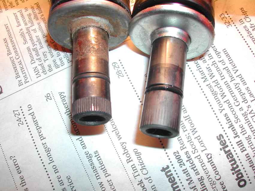
So I decided to strip the bearing & oil-seal etc from the new pump, including the 6-vane impellor to replace the 12-vane that had been fitted in 1982. Disassembly of the new pump revealed much shallower knurling than on the old shaft:
Knurling on shaft
The other noticeable difference was that the depth of machining of the gears on the old shaft was deeper than on the new:
Machining on gears
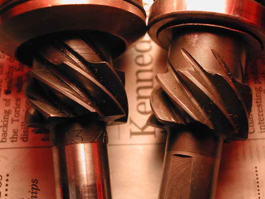
The old shaft also had markings: ND3 ZEPHYR which were absent on the new one.
Before you extract the pump, lock the crankshaft to prevent rotation. |
The graphite bearing (closest to vane assembly) appeared to be decidedly worn and seemed to be passing water to the water flinger below. |
Subsequent examination showed the graphite seal to be in quite good shape? |
12-vane pump |
12-vane rotor detail |
Side view |
 |
 |
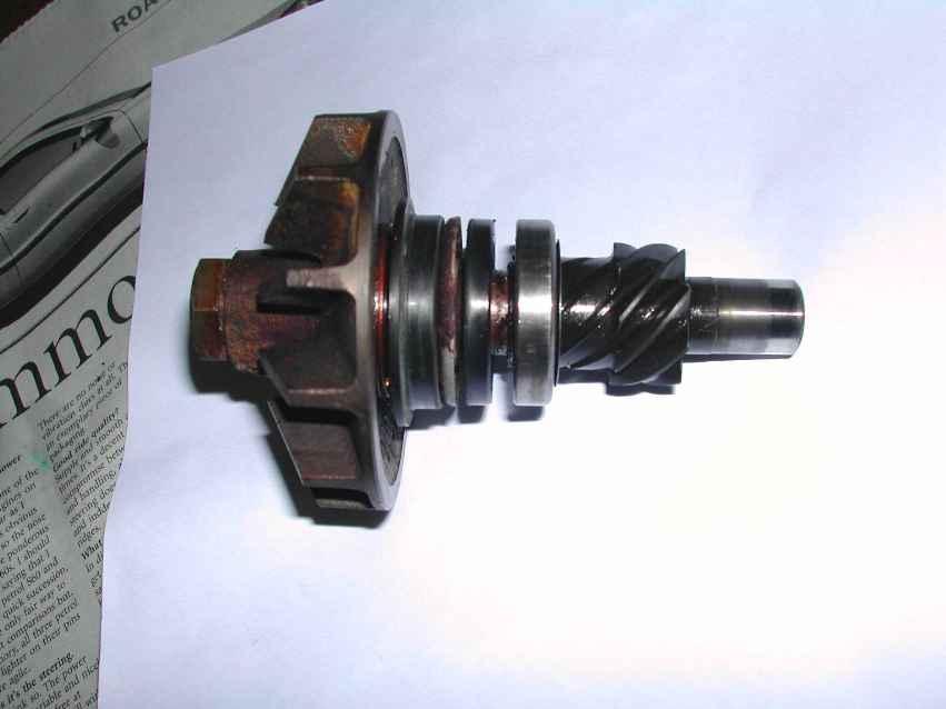 |
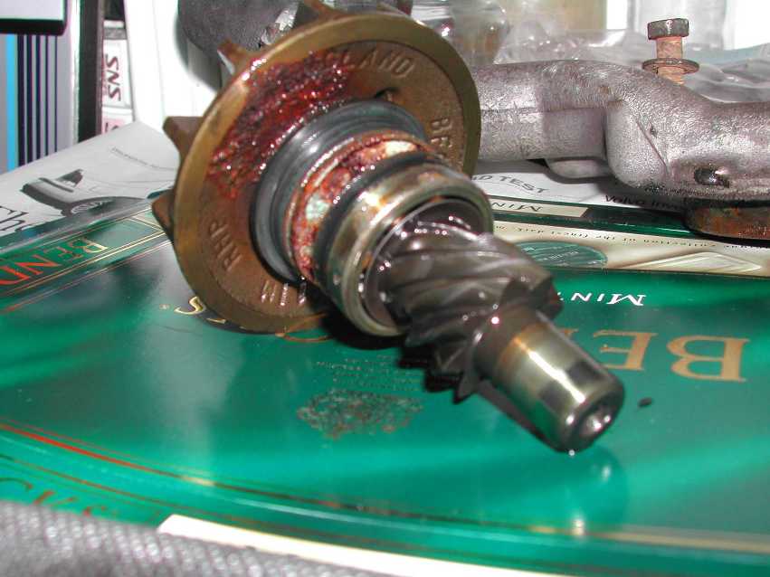
Note order of rotor, graphite seal, water thrower, oil seal, ball bearing.
Note corrosion on shaft & water thrower indicating that graphite seal is passing water?
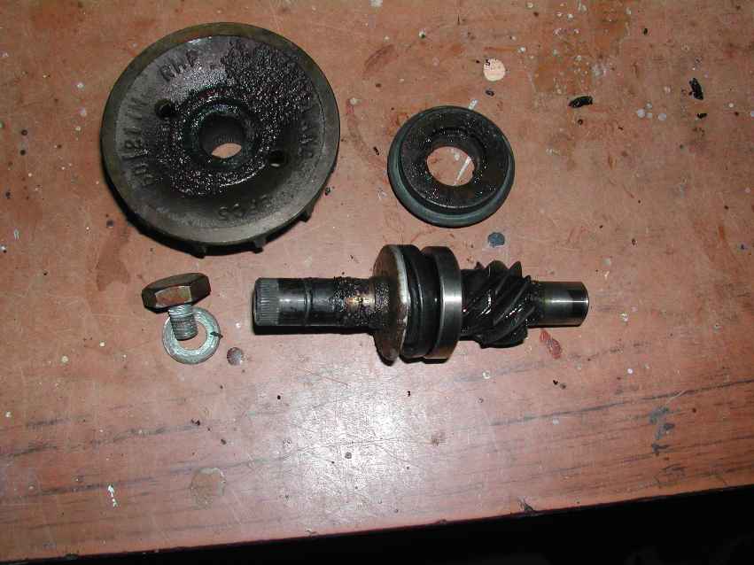
Water pump parts
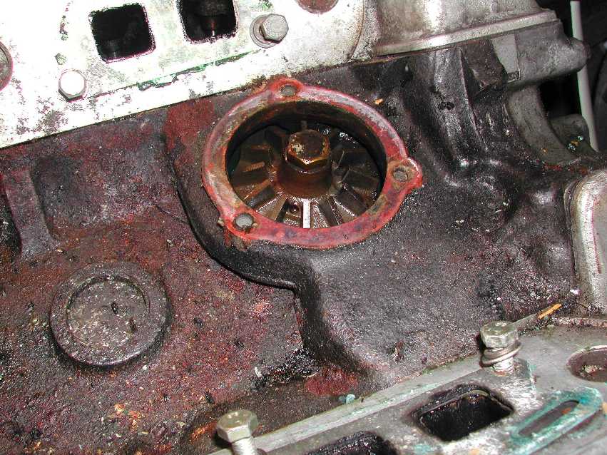
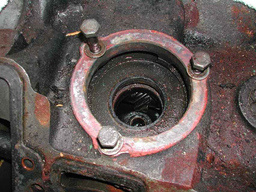
Close-up showing the jack-shaft (just). Note the brass housing remained in place.
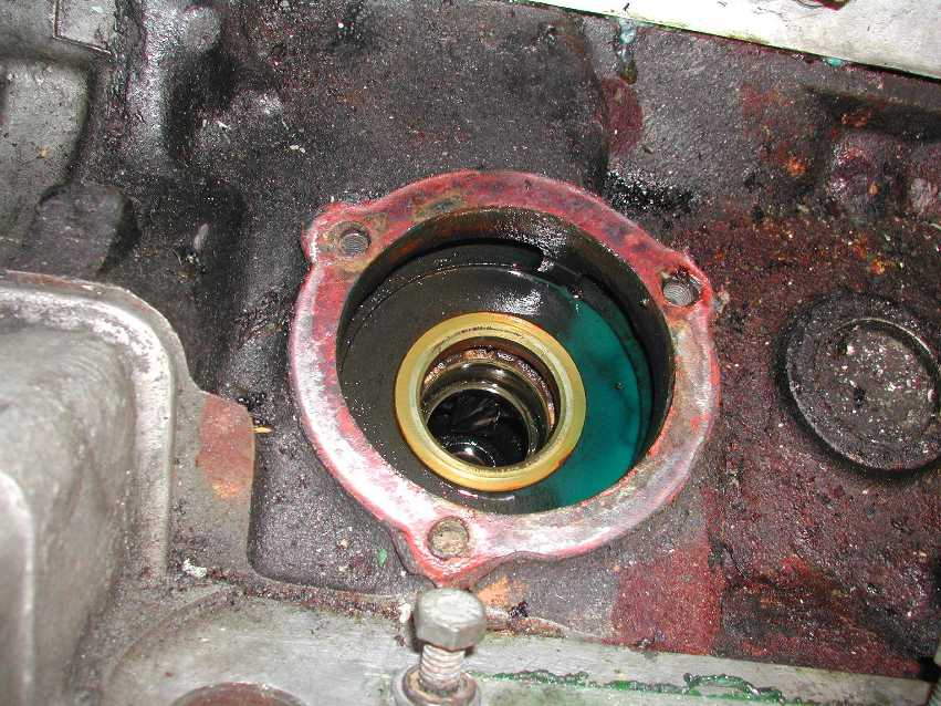
I had trouble removing this: after posting the problem on the Discussion Forum on TriumphStag.net, I got a reply within an hour or so suggesting the use of a slide hammer. Alan very kindly provided a proto-type which worked a treat and fully exposed the jack-shaft.
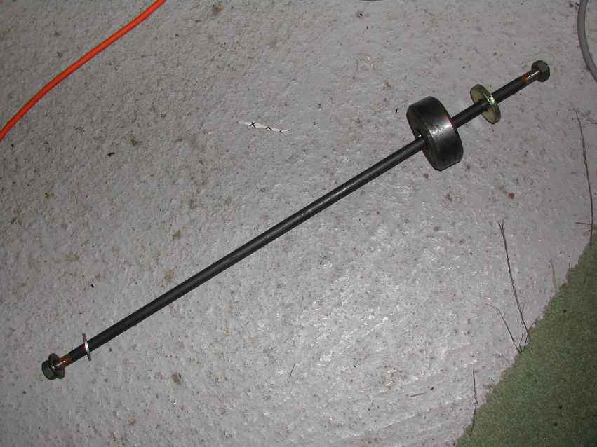
Makeshift slide-hammer |
Jack-shaft exposed |
 |
 |
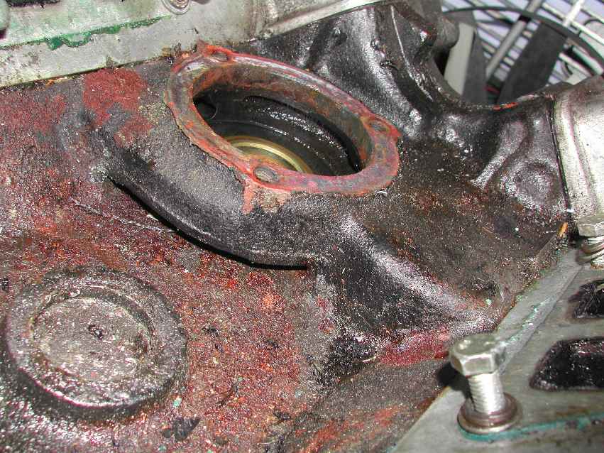
Any water that passes the graphite seal is thrown out via the brass housing and the slot in the crankcase to the top of the Vee:
Water escape slot
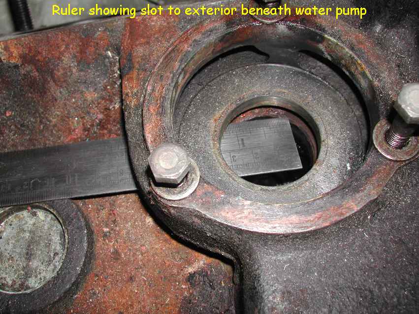
The slot is demonstated by a 12" ruler which can be passed right through when the brass housing is removed. |
In my case, I think most of my water loss was from the inlet manifold waterways, since the graphite seal appeared to be in good shape. Anti-freeze was not apparent in the vicinity of the escape slot. |
Direction of water flow: the Workshop Manual indicates (page 82.00.03) that water is drawn from the rear of the LH cylinder head into the heater, and returns to the top (suction) side of the pump via the metal pipe and pump housing. The heater return mingles with water returning from the radiator via the bottom hose and water via the bypass hose when the thermostat is closed. |
When the thermostat is open, the pump forces most of the hot water around the engine and through the inlet manifold to the radiator via the top hose. |
Schematic of water system
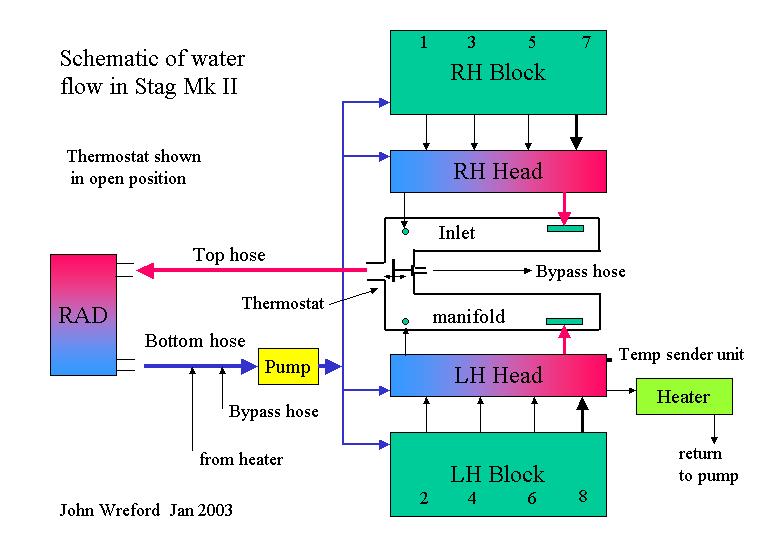
This diagram is a pre-cursor to my attempt to discover if gasket hole alignment is critical for even temperature distribution. Apparently, it is not, but I have yet to pinpoint the reason for my occasional overheating.
Close the page