Stag Hazard Switch
.gif)
I have been replacing the faded dashboard of my Stag with a Burr Walnut replacement which I obtained
from an abandoned restoration project..
My original didn’t have a Hazard Switch on the face of the dashboard, so a P.O. had fitted a Hella Hazard Switch.
It had certainly seen better days. It was held together with tape, and the wiring was just as bad!
Twisted wires and bits of sticky tape all over the place.
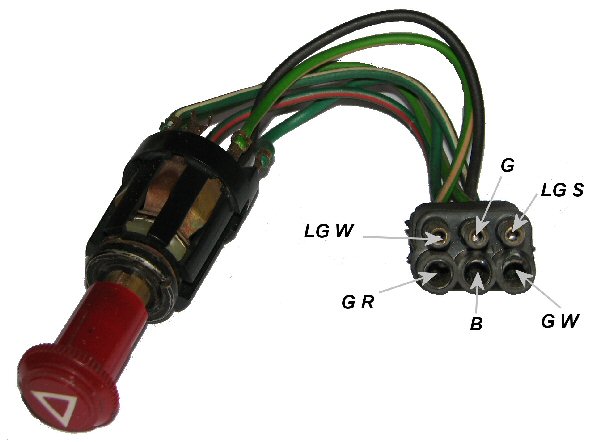
The new dashboard had a switch built in. How did it work? How do I connect it to my car? I couldn’t find
any diagrams to show the wiring so I set out with my meter to see how the switch was connected internally.
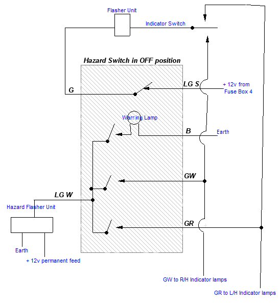
I found that the G & LG S wires were connected when the switch was OFF and disconnected when the switch was ON.
The normal Indicator flasher relay is connected in series with these.
When the hazards are on, the normal indicator flasher unit is disconnected.
The other wires are isolated when the switch is OFF.
When the switch is ON the LG W from the Hazard Flasher Unit is connected to the GR and GW wires.
These are connected to the wiring loom going to the Indicator Lamps.
It also connects to the warning lamp in the switch.
I bought a new Land Rover heavy duty flasher unit from Fleabay. £25 value for £4 delivered. Bargain!
This is required to power all the lamps (9 of them).
CONNECTING:
Colour code: B – Black, G – Green, LG – Light Green, R – Red, S – Slate, W – White, .
Connect a brown wire from a permanently live fuse (fuse box 2) to the +ve/49 of the Hazard Relay.
Connect the –ve/31 of the Hazard Relay to an Earth
Connect the Load/49a of the Hazard Relay to the LG W of the Hazard Switch.
Disconnect the 2 x G wires from the normal Indicator Flasher Unit and connect them to the LG S of the Hazard Switch.
Connect the G wire of the Hazard Switch to the normal Indicator Flasher Unit (where the 2 x G wires came from)
Connect the GR & GW wires of the Hazard Switch to the corresponding GR & GW wires in the loom. These go to the indicator lamps.